Loading Condition Builder (Option 1: Draft-driven)
Step 1 — Drafts & water density
Step 2 — Cargo holds (grain / bulk)
Set SF (m³/t). For PARTIAL, enter ullage (m) (or level) and the app reads Volume/VCG/VHM from the hold tables.
| Hold | Status | Ullage (m) | Level (m) | Volume (m³) | VCG (m) | Weight (t) |
|---|
Step 3 — Tanks (ballast / wing / peaks)
Linear Level↔% via hmax (editable). FSM sum is shown for partly filled tanks (used later for KGv).
| Tank | Cap (m³ / t) | LCG/VCG/TCG | Hmax (m) | % | Level (m) | Weight (t) |
|---|
Result
GMt is computed as GMt = KMt − KGv, where KGv = KG + (ΣFSM / Δ) (FSM applied for slack tanks).
Grain Stability – Requirements, Sources & How to Calculate (Student Guide)
The following checks come from the International Code for the Safe Carriage of Grain in Bulk (the International Grain Code, adopted under SOLAS Chapter VI). In this module we assume a conservative (worst‑case) grain shift and verify that the ship still has adequate stability.
A) The 3 mandatory Grain Code criteria
1) Heel angle due to grain shift
Where it comes from: If the vessel heels, the grain surface can shift to the low side. This creates a destabilizing heeling moment and therefore a heeling arm.
How to check on a stability (Reed) diagram: Plot the ship’s righting arm curve (GZ) and the grain heeling arm curve on the same axes. The heel angle is taken where the two curves are equal (GZ = heeling arm) — that is the equilibrium heel due to grain shift.
Requirement: Heel angle ≤ 12° or ≤ deck edge immersion angle (whichever is smaller).
2) Residual (net) area between GZ and heeling arm
Where it comes from: The ship must retain enough dynamic stability (energy reserve) after the assumed grain shift to recover from rolling and external disturbances.
How to calculate / check: Determine the net area between the curves (GZ − heeling arm) from 0° up to the smallest of: the angle of maximum difference between ordinates, 40°, or the flooding angle θ1.
Residual area  A = ∫ (GZ(θ) − LH(θ)) dθ     with θ in radians
deg → rad:  θ(rad) = θ(deg) × π / 180
Residual area info (Show / Hide)
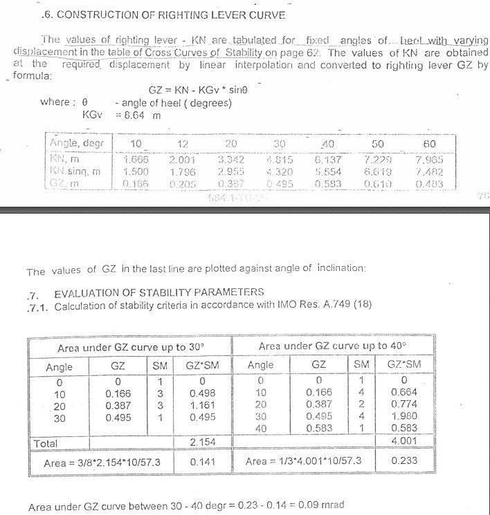
Example of numerical integration of the GZ curve. Area is calculated by summing segments and converting degrees to radians. The same principle is used when calculating the residual (net) area between the GZ curve and the grain heeling arm curve.
Requirement: Residual area ≥ 0.075 m·rad.
3) Corrected GM (including Free Surface Effect)
Where it comes from: Liquids in partially filled tanks create a free surface that reduces stability. Therefore the Grain Code requires the initial metacentric height corrected for free surface effects.
GM = KM − KG
FSC (free-surface correction) = ΣFSM / Δ
GM_corrected = GM − FSC
Requirement: GMcorrected ≥ 0.30 m.
B) Reed grain stability diagram – how the curves are built
Many textbooks show the Grain Code check using a Reed stability diagram. The key idea is simple: compare the ship’s righting ability (GZ curve) against the grain heeling effect (LH curve).
1) Righting arm (GZ) curve
The GZ curve comes from the ship’s hydrostatic data (KN values / cross curves) and the loading condition (KG). In practice: for each heel angle θ, compute GZ from KN and KG (and any corrections required by your method).
2) Grain heeling arm (LH) curve
The Grain Code assumes a calculated heeling moment due to grain shift. Converting moment to an arm uses the ship displacement:
LH(θ) = M_grain(θ) / Δ
where:
  M_grain(θ) = total heeling moment due to assumed grain shift (t·m or kN·m)
  Δ = displacement for the loading condition (t or kN)
The detailed calculation of M_grain depends on hold geometry, grain properties (stowage factor), and the assumed shift defined by the Grain Code. Your ship’s Grain Loading Book provides the approved method and constants.
3) Deck edge immersion angle
The deck edge immersion angle is the heel angle where the deck edge touches the waterline. It can be determined from the ship’s geometry/hydrostatics (or from the approved stability book). It is used as an upper limit because once the deck edge immerses, downflooding risk increases rapidly.
Reed diagram (Show / Hide)
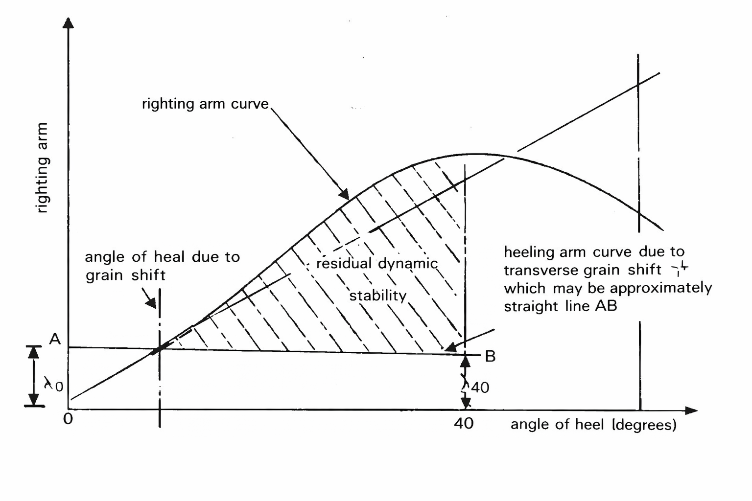
Reed diagram (IMO Grain Code) – explanation of the righting arm curve (GZ), grain heeling arm due to transverse grain shift, residual dynamic stability area, and the 40° limit used for area evaluation.